FloorPlan-DSL
How to specify an indoor environment
The ExSce-FloorPlan DSL is a domain-specific language and tooling for specifying and generating indoor environments. In this tutorial we are going to go over the most important concepts to model a concrete floor plan.
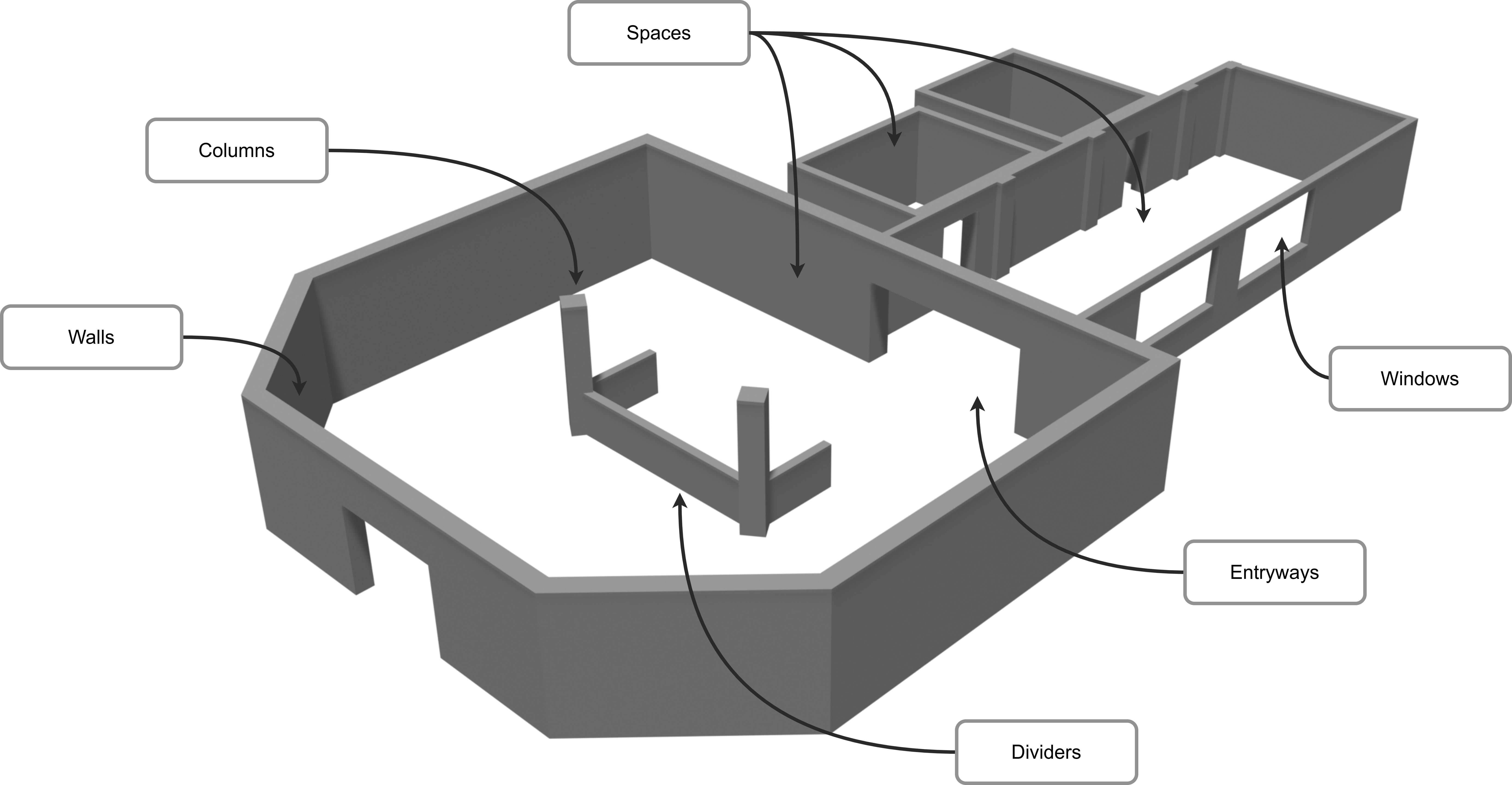
The goal of this tutorial is to create the environment above. We will go over concepts such as Spaces, Entryways, and other features in order to specify a specific environment.
Concepts available
Let’s do a review of the most important concepts when modelling an indoor environment:
-
Spaces: these are the central concepts when modelling. This concept allows you to model any space in a floor plan: a room, a hallway, an intersection, a reception, and any other space that is surrounded by walls.
-
Walls: walls surround the spaces, and these are not modelled directly. When modelling a space, you select the shape of the space, and the walls are created automatically when interpreting the model.
-
Entryways and Windows: These are openings in the walls that allow you to connect two spaces.
-
Column and Dividers: These are features of the environments that are usually located freely in space or next to walls. Both cases can be modelled using the language.
Modelling
Modelling an indoor environment consists of declaring the Spaces, Entryways, Windows, Columns, and Dividers; and specifying their location in the environment. Each of these concepts is modelled by specifying its shape and other attributes such as thickness or height. Specifying the location is simple, but requires some background.
Conventions
In the examples below, you will notice some conventions for the frames of reference of each element.
Z-axis
Most of the descriptions assume you are modelling the floor plan using a top-down view, with the z axis pointing outside of your screen.
Colors
The x axis is red and the y axis is green.
Space frames
Each space has its origin frame in its center. The x axis is positive to the right side and the y axis towards the top.
Polygon coordinates are always defined with respect to the center of the space and considering the inside of the room.
Walls
The wall frame is located on the wall edge inside of the room. The thickness of the wall is applied in its y (positive) direction of the wall frame.
Locations
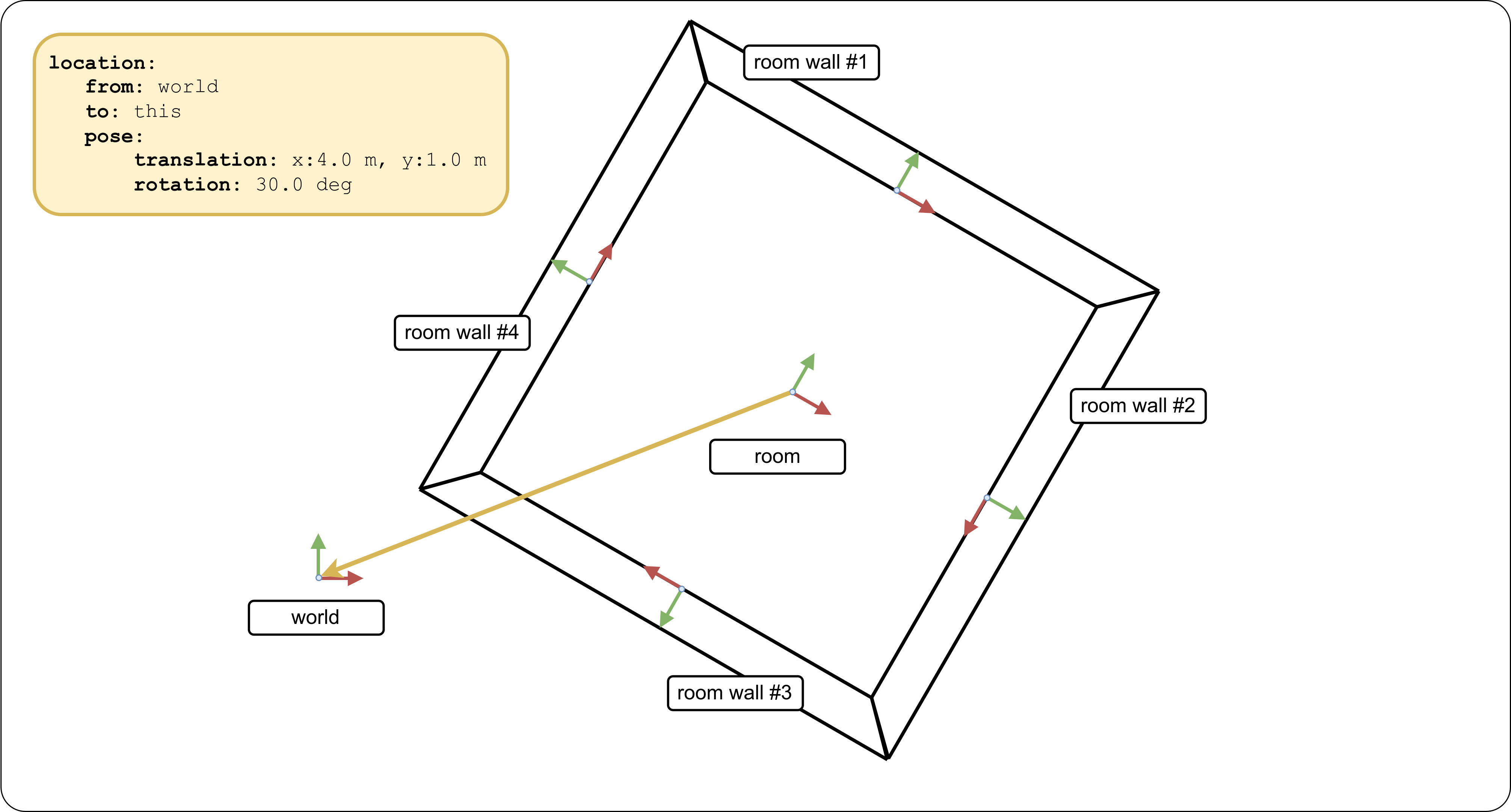
The location of any space or feature is specified by a translation and rotation with regards to a frame of reference. There are multiple frames of references that can be chosen for this. Apart from the world frame, each space has N + 1 frames of references that can be selected, where N is the number of walls.
For each wall in the space, there is a frame located in the middle of the wall, with the x axis going along the wall and the y axis perpendicular to the wall. From the perspective of being inside the room looking into one of the walls: Positive values in the x axis are located from the centre to the right, and negative values in the opposite direction. Whereas the positive direction from the y axis moves away from you and the negative direction moves closer. The frame is located at floor level, meaning that for the z axis only positive values are above the floor.
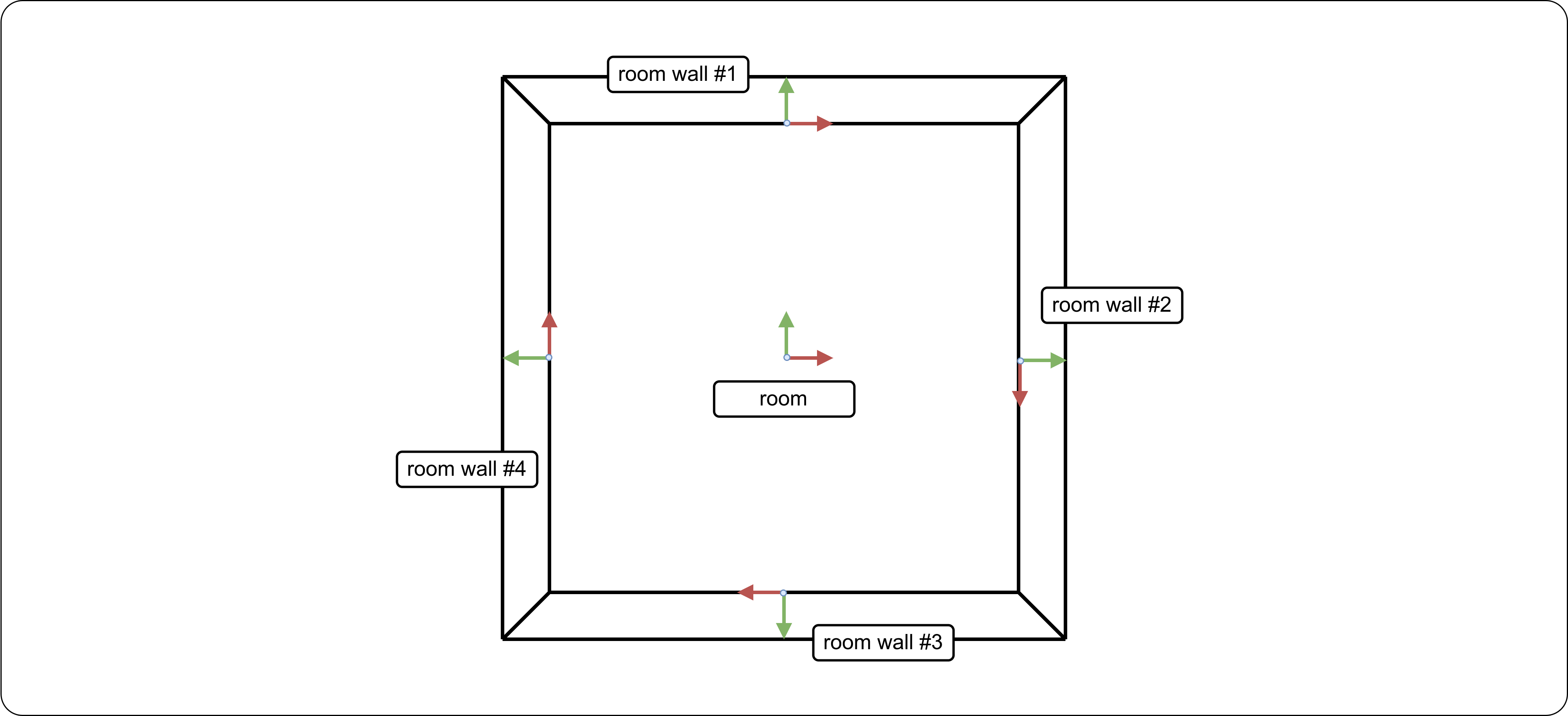
The image above illustrates a room with all of its frames. Each wall has an index, so you can select the frame of reference by specifying the index of the desired wall: <name of space>.walls[<index>]. You can also select the center frame of the space by just referring to the name: <name of space>. You may also select the world frame with the world keyword.
A space requires two frames in order to specify a location: A reference frame where the translation and rotation are specified from, and the frame that will get translated and rotated.
Using the world frame
You can select the world frame as your frame of reference by using the keyword world. You may only use this frame for locating spaces. Any other feature or entryway must be specified by either the center frame or one of the walls. Should be noted that you can use the this keyword to reference a frame when you are inside the scope of the space that frame belongs to.
location:
    wrt: world
    of: this
    translation: x:3.0 m, y:4.0 m
    rotation: z: 45.0 deg
Using two wall frames
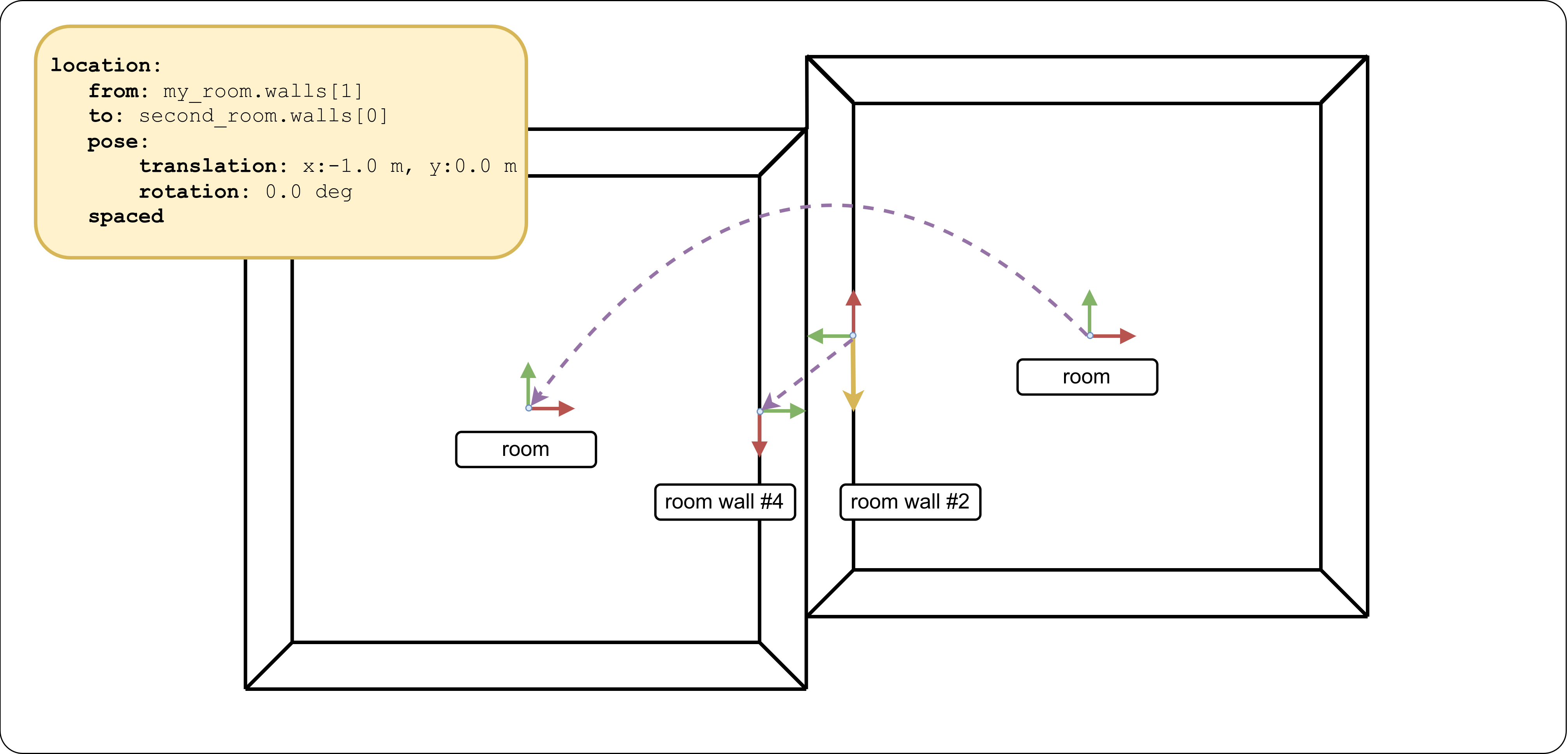
You can also use two wall frames to define locations. When you model a location using two wall frames, the default behaviour is to do an extra 180 degree rotation of the space you are locating so that the two spaces are not overlapping. Depending on the two walls that are chosen, the results can be different, as illustrated in the two next examples
location:
    wrt: my_room.walls[1]
    of: second_room.walls[0]
    translation: x:-1.0 m, y:0.0 m
    rotation: z: 0.0 deg
    spaced
location:
    wrt: my_room.walls[1]
    of: second_room.walls[1]
    translation: x:0.0 m, y:0.0 m
    rotation: z: 0.0 deg
    spaced
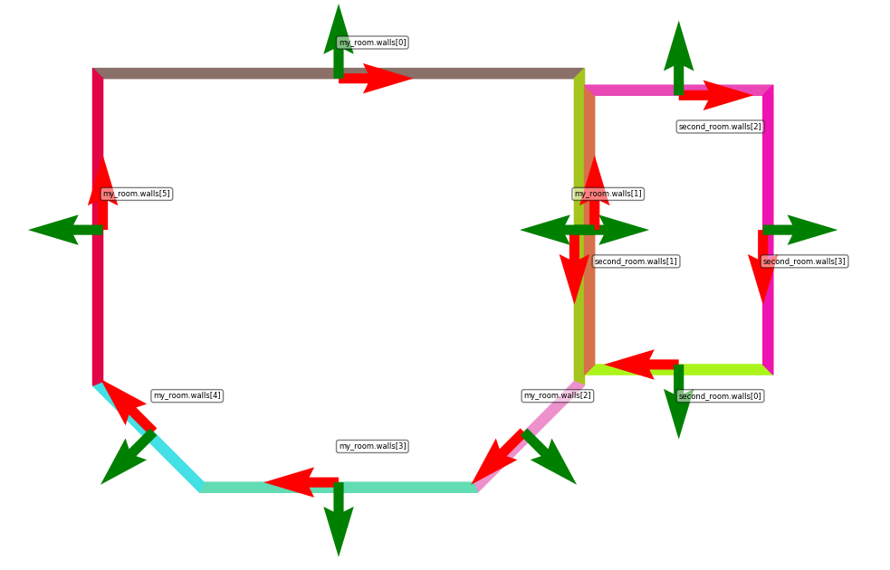
The flag spaced is used to tell the interpreter to calculate the combined thickness of the two walls, and space the two rooms accordingly. When not present, the two rooms are not spaced correctly, as seen in the next figure.
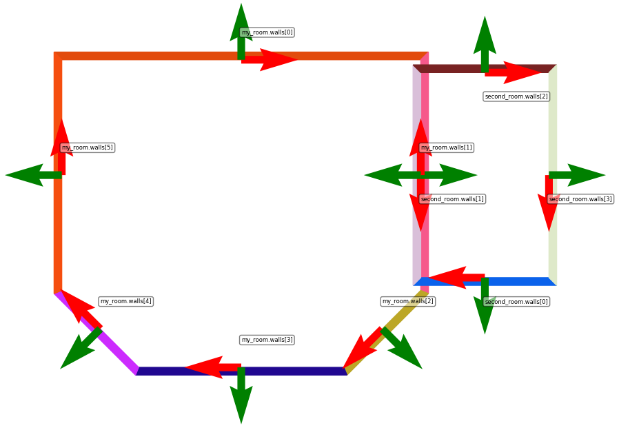
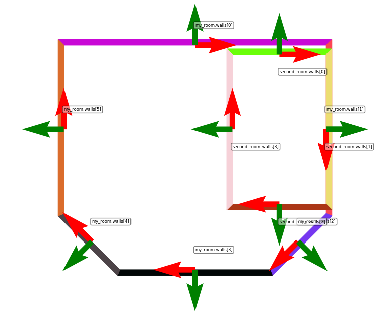
Similarly, the default alignment behaviour can be disabled by using the not aligned flag, so that the two rooms overlap.
location:
    wrt: my_room.walls[1]
    of: second_room.walls[1]
    translation: x:0.0 m, y:0.0 m
    rotation: z: 0.0 deg
    not aligned
Features
The language enables the modelling of doorways, windows, columns, and dividers. Features such as columns or dividers are always defined within a space scope, so you can use the “this” keyword to refer to the walls inside the space.
Column wall_column:
    shape: Rectangle width=0.5 m, length=0.3 m
    height: 2.5 m
    location:
        wrt: this.walls[3]
        translation: x:7.0 m, y:0.0 m, z: 0.0 m
        rotation: z: 0.0 deg
Entryways and windows are specified outside of the scope of the space, after all the spaces in the floorplan have been specified. These features create the openings in the walls required to connect two spaces or one space with the “outside”.
Entryway doorway:
    shape: Rectangle width=1.0 m, height=1.8 m
    location:
        in: my_room.walls[0] and second_room.walls[1]
        translation: x: -1.0 m, y: 0.0 m, z: 0.0 m
        rotation: z: 0.0 deg
Whenever an entryway or window is located in a wall shared by two spaces, you must specify the two walls that will be opened by the entryway or window (my_room.walls[0] and second_room.walls[1]). However, The location is specified with regards to the first frame specified, in the example above it would be my_room.walls[0].
Modelling the example
Now that we have reviewed all of the important concepts, we can put them together in a model. The finished model for this tutorial is available here. In this section we will go over the model section by section with some explanations when needed.
Floor plan: hospital

    Space reception:
        shape: Polygon points:[
            (-7.0 m, 6.0 m),
            (7.0 m, 6.0 m),
            (7.0 m, -3.0 m),
            (4.0 m, -6.0 m),
            (-4.0 m, -6.0 m),
            (-7.0 m, -3.0 m)
        ]
        location:
            wrt: world
            of: this
            translation: x:0.0 m, y:-5.0 m
            rotation: z: 45.0 deg
Each floor plan has a name, which gets used to identify all the artefacts that get generated. The reception space has a custom polygon as shape, so we specify all the points to bound it. Every pair of points is a wall, with the last point and the first point being the final wall to close the polygon (i.e. no need to repeat the first point at the very end). From the world frame, this space is translated -5 metres in the y axis and rotated 45 degrees w.r.t. the z axis.
        ...
        wall:
            thickness: 0.40 m
            height: 3.0 m
        features:
            Column central_left:
                shape: Rectangle width=0.5 m, length=0.5 m
                height: 3.0 m
                location:
                    wrt: this
                    translation: x:-2.5 m, y:0.0 m
                    rotation: z: -35.0 deg
        ...
The reception space will have a wall thickness of 0.4 metres and a wall height of 3 metres. These values don’t have to be specified for every space, as default values will be set later for all spaces. Nested in the feature concept, columns and dividers can be specified. The reference frame for these is always part of the space (either the space frame or a wall frame of the reception space)
    Space hallway:
        shape: Rectangle width=5.0 m, length=14.0 m
        location:
            wrt: reception.walls[0]
            of: this.walls[2]
            translation: x:2.0 m, y:0.0 m
            rotation: z: 0.0 deg
            spaced
        ...

    Space room_A:
        ...

    Space room_B:
        ...
The hallway is located using two wall frames, and the flag spaced is present so that the interpreter calculates spacing necessary to avoid overlapping in between the spaces. Two other spaces also get defined in a similar way.
    Entryway reception_main:
        shape: Rectangle width=2.5 m, height=2.0 m
        location:
            in: reception.walls[3]
            translation: x:0.0 m, y: 0.0 m, z: 0.0 m
            rotation: y: 0.0 deg

    Entryway reception_hallway:
        shape: Rectangle width=4.0 m, height=2.0 m
        location:
            in: reception.walls[0] and hallway.walls[2]
            translation: x: 2.0 m, y: 0.0 m, z: 0.0 m
            rotation: y: 0.0 deg

    ...
    Window hallway_window_1:
        shape: Rectangle width=3.0 m, height=1.5 m
        location:
            in: hallway.walls[1]
            translation: x: 3.0 m, y: 0.0 m, z: 0.8 m
            rotation: y: 0.0 deg
Two entryways and one window are modelled, each with a unique name. In the case of the second entryway, since it connects two spaces we must specify the two walls where the entryway is located. Notice that for windows we have to specify a translation in the z axis.
    Default values:
        walls:
            thickness: 0.23 m
            height: 2.5 m
At the very end of the model the default values for all the spaces must be specified.